How to video - Installation of the captive ending
How to video - Removal of the captive ending
Installation on AC218 (1.5in) actuator
Installation on AC231 (3in) actuator
Installation on AC360 (6in) actuator
General information
The D-BOX captive ending is a 2 components assembly:
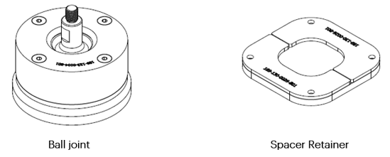
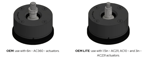
Ball joints
There are 2 models of ball joints:
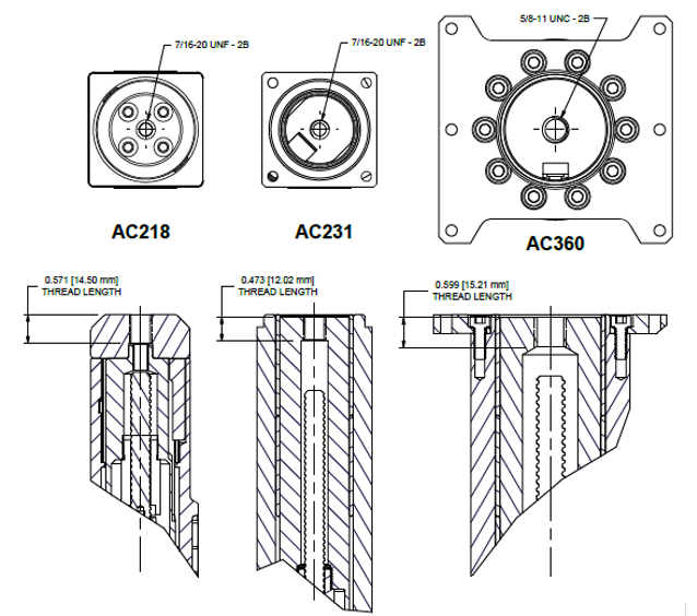
The thread of the captive endings for each actuator is as follow:
Spacer Retainer
The spacer-retainer allows specific movements of the ball joint on both x and y axes, thus eliminating any constraints during the movement of the platform. There are 3 models of spacer retainer. All spacer retainers can be fitted on any model of ball joint.
 |
0 axis |
allowing no movement in x and y axis. |
 |
1 axis |
allowing movement only on 1 axis (x or y). |
 |
2axes |
allowing movement on 2 axes (x and y). |
Caution : respect the orientation to avoid any damage to the components of the platform.
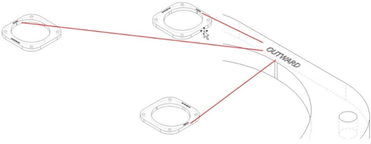
Here are some spacer retainer configurations.
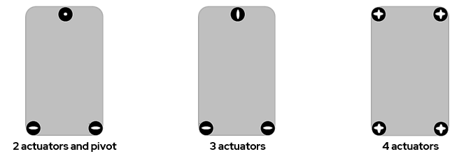
To help with positioning, the spacer retainer is marked OUTWARD on its top surface.
Tools required
 |
Short Hex Key
|
 |
Wrench 5/8 |
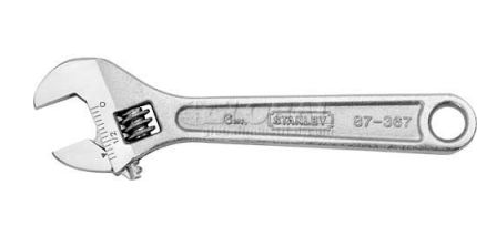 |
Adjustable Wrench or Wrench
|
How to video - how to install a captive ending?
How to video - how to remove a captive ending?
Installation on AC218 (1.5in) actuator
Note : make sure all the parts are clean before installation.
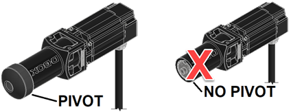
Caution: Never operate the AC218 actuator without the pivot installed. Operating the AC218 actuator without the pivot leads to irreparable damages to the actuator.
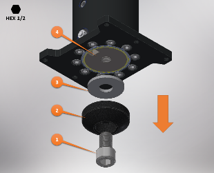
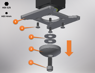
| Step 1: |
Pull the piston out of its body until you can access the flats on both side of the shaft. Position the wrench around the flat spot to hold the piston while performing next step and prevent rotation. |
| Step 2: |
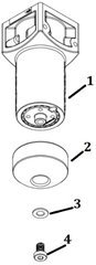
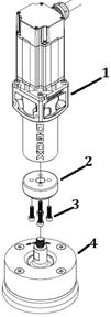
Unscrew bolt (4) with the ½ hex key and remove washer (3) and pivot (2) from the actuator (1).
|
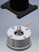
| Step 3: |
Apply Threadlocker Loctite 263 to the threaded section of bolts (3) and ball joint (4). Install pivot (2) on actuator (1) with bolts (3). Torque bolts to 50 lbf in. Screw the threaded section of ball joint (4) in the actuator (3). Use a torque wrench with a 5/8 crow foot socket to tighten the ball joint (4) in the actuator. Torque to 170 lbf in.
|
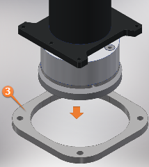
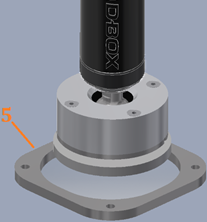
| Step 4: |
Place spacer (5) at its required location. Make sure the holes in the spacer are aligned with the holes in the floor and place the actuator and ball joint assembly in spacer (5).
|
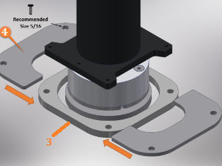
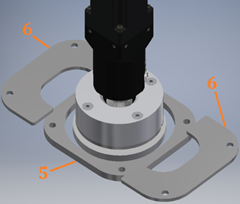
| Step 5: |
Slide retainers (6) on spacer (5) and in the slot on the ball joint.
|
| Step 6: |
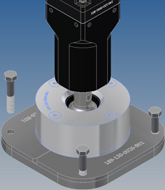
Align the holes in the retainers with the holes in the spacer. Use 5/16 bolts to tighten the spacer and retainers to the floor. NOTE: the way the ball joint is anchored to the floor is the same for all actuators – 1.5”, 3”, and 6”.
|
Installation on AC231 (3in) actuator
Note : make sure all the parts are clean before installation.
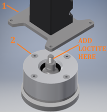
| Step 1: |
Pull the piston out of its body until you can access the flats on both side of the shaft. Position the wrench around the flat spot to hold the piston while performing next step and prevent rotation. |
| Step 2: |
Unscrew bolt (1) with the 3/8 hex key and remove pivot (2) and spacers (3) from the actuator. Unscrew bolt (4) with the 4mm hex key and (optional) remove H-bracket (5) from the actuator.
|
| Step 3: |
Add Threadlocker Loctite 263 to the threaded section. Screw the threaded section in the actuator (1). Use a torque wrench with a 5/8 crow foot socket to tighten the ball joint assembly (2) in the actuator. Torque to 170 lbf in.
|
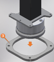
| Step 4: |
Place spacer (3) at its required location. Make sure the holes in the spacer are aligned with the holes in the floor and place the actuator and ball joint assembly in spacer (3).
|
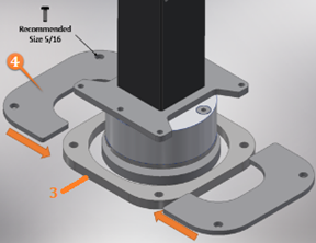
| Step 5: |
Slide retainers (4) on spacer (3) and in the slot on the ball joint. Align the holes in the retainers with the holes in the spacer. Use 5/16 bolts to tighten the spacer and retainers to the floor.
|
Installation on AC360 (6in) actuator
Note : make sure all the parts are clean before installation.
| Step 1: |
Pull the piston out of its body until you can access the flats on both side of the shaft. Position the wrench around the flat spot to hold the piston while performing next step and prevent rotation. |
| Step 2: |
Unscrew bolt (1) with the ½ hex key and remove pivot (2) and spacer (3) from actuator (4).
|
| Step 3: |
Add Threadlocker Loctite 263 to the threaded section. Screw the threaded section in the actuator (1). Use a torque wrench with a 5/8 crow foot socket to tighten the ball joint assembly (2) in the actuator. Torque to 170 lbf in.
|
| Step 4: |
Place spacer (3) at its required location. Make sure the holes in the spacer are aligned with the holes in the floor and place the actuator and ball joint assembly in spacer (3).
|
| Step 5: |
Slide retainers (4) on spacer (3) and in the slot on the ball joint. Align the holes in the retainers with the holes in the spacer. Use 5/16 bolts to tighten the spacer and retainers to the floor.
|